IPSec Mobile to an other network IPSEC
Good morning, sir,
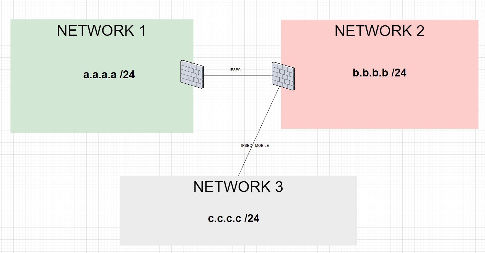
Here is the network diagram of my infrastructure:
Network 1 = 192.168.26.0/24
Network 2 = 172.16.26.0/24
Network 3 = 14.15.16.0/24
Network 1 --> Network 2 OK
Network 1 --> Network 3 NO
Network 2 --> Network 3 OK
Network 2 --> Network 1 OK
Network 3 --> Network 1 NO
Network 3 --> Network 2 OK
Is it possible to create a phase 2 that mentions access to Network 1 through the normal IPSec tunnel?
Network 3 = Mobile it created by Pfsense of network 2
Please also mark the comments that contributed to the solution of the article
Content-Key: 559328
Url: https://administrator.de/contentid/559328
Printed on: April 18, 2024 at 13:04 o'clock
11 Comments
Latest comment
Please, don't DM me for replies to forum posts.
The link you posted was about pfsense and FBs ... but nevermind...
Still, you're using a non -RFC1918 Network, is this intentional?
Hello,
You answered my question concerning the connection problem between the Ipsec networks.
Except that I don't have a FritzBox, I only use pfsense.
Except that I don't have a FritzBox, I only use pfsense.
The link you posted was about pfsense and FBs ... but nevermind...
Still, you're using a non -RFC1918 Network, is this intentional?
Looks like network 1 and network 2 are VPN connected with a simple site to site tunnel, both on pfSense hardware.
Whats a bit unclear here is the network 3 site ?
The main question is why this is named IPsec mobile ?
IPsec mobile is usually used for mobile clients dialin like VPN onboard software clients in end devices. It does in general NOT do a site to site connection with routing as shown here in the drawing and is maybe a VPN misdesign.
Main question which still remains is if this "mobile" is just a typo in the drawing and the tunnel to network 3 is a site to site tunnel as well.
Or, if mobile IPsec is really in use here to establish the link. As said before from a design perspective its not correct that way but probably may work.
The other question is what kind of VPN hardware we are talking about here at network 3 ? pfSense as well ??
And finally: Is mobile IPsec here at network 3 really mandatory or can it just be also a static site to site VPN like in the connection between 1 and 2 ?
In the latter case the config would be of course very easy
The threadowner should answer this before we dig deeper into this issue ?
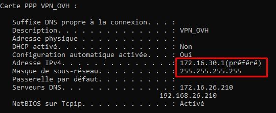
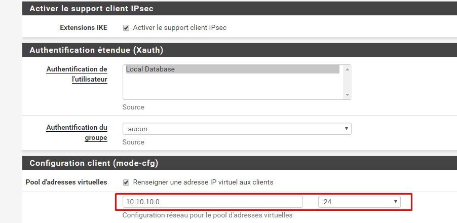
In network 3 there is no pfsense it is the pfsense of network 2 which creates a network "172.16.30.0/24" for the "mobile" remote users.
So to make it clear for us. network 3 is just a mobile user dialin in to the pfSense on 2. Is that correct ?So more or less a classic VPN dialin solution what is described here in this tutorial:
IPsec IKEv2 VPN für mobile Benutzer auf der pfSense oder OPNsense Firewall einrichten
Do you use IKEv2 here to cover Win 10 users with their onboard clients or do you still use standard IKEv1.
I will post some screenshots for the solution over the weekend.
And here is your solution !
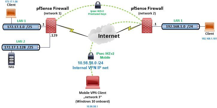
The setup this scenario is based on, reflects pretty much your design:
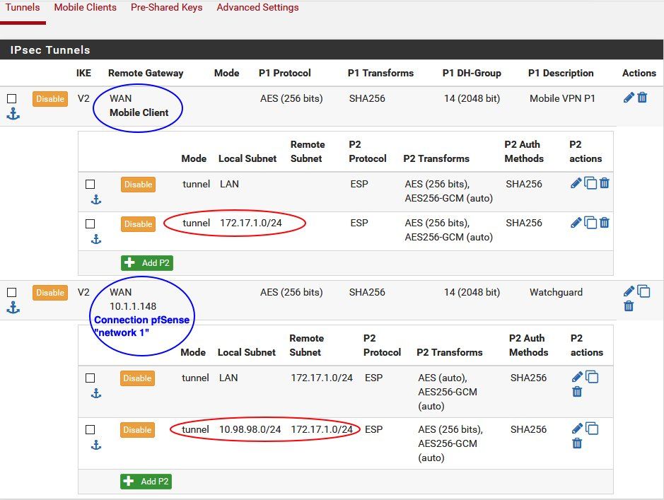
Due to the fact that you need to tunnel the VPN dialin IP network you need to add a second P2 entry either into the static tunnel to network 1 as well as into both tunnels on the pfSense at network 2.
The network 2 pfSense must have two Phase 2s defined for both tunnels !
The static one which serves network 1 and the tunnel which servers the mobile VPN users network 3.
The above setup has different network IP settings which is just cosmetic and you have to modify them to your individual settings.
First P2 type is set to "network" and local:172.17.1.0 /24, remote:192.168.1.0 which sends both local networks into the static tunnel.
Second P2 type set as well to "network" and local:172.17.1.0 /24 remote:10.98.98.0 /24 which sends the 10.98.98.0 VPN client network into the tunnel
Here its more or less the same.
First P2 entry in the mobile client tunnel serves the local network to the clients.
Second P2 entry in the mobile client tunnel serves the remote network at network 1 to the clients.
Same with the counterpart of the static network tunnel to network 1.
Client VPN dialin setting is fully based on this local tutorial which has all the details:
IPsec IKEv2 VPN für mobile Benutzer auf der pfSense oder OPNsense Firewall einrichten
Both networks should be provided to the clients.
Optionally you should set a static route into the VPN client connection on the Windows 10 site with Power Shell (Admin mode): Add-VpnConnectionRoute -ConnectionName "pfSense" -DestinationPrefix 192.168.1.0/24 -PassThru
and additionally
Add-VpnConnectionRoute -ConnectionName "pfSense" -DestinationPrefix 172.17.1.0/24 -PassThru
This is usually not mandatory cause the pfSense mobile connection setup will provide both configured P2 networks automatically into the client routing table during client tunnel establishment. But Windows is here a bit "sensitive", cause the internal routing table needs administrator rights. So its more waterproof to additionnally add that route into the VPN client setup here to make sure it works under all circumstances.
Checking the client routing table while the client is connected:
As you can see route entry "172.17.1.0 255.255.255.0 Auf Verbindung 10.98.98.1 36" shows that all traffic from the VPN client to network 1 networks (and of course 192.168.1.0 for local network 2 LAN !) is send into the client VPN tunnel (10.98.98.1) !
VPN client has gotten the right IP address (10.98.98.1) from the internal VPN IP which could also be seen in the above routing table:
And finally the Ping check into the local LAN on network 1:
A Ping to a local switch management IP address 172.17.1.2 was also successful !
Conclusion:
Works as designed !
And...if it works for you as well, feel free to post or link it to the Netgate forum as well !!
The setup this scenario is based on, reflects pretty much your design:
Due to the fact that you need to tunnel the VPN dialin IP network you need to add a second P2 entry either into the static tunnel to network 1 as well as into both tunnels on the pfSense at network 2.
The network 2 pfSense must have two Phase 2s defined for both tunnels !
The static one which serves network 1 and the tunnel which servers the mobile VPN users network 3.
The above setup has different network IP settings which is just cosmetic and you have to modify them to your individual settings.
- Internal IPsec IKEv2 VPN IP network: 10.98.98.0 /24
- Local networks at network 1: 172.17.1.0 /25 and 172.17.1.128 /25. (Both combined in the IPsec P2 settings under a /24 mask !)
- Local network at network 2: 192.168.1.0 /24
 1.) Static tunnel at pfSense location "network 1":
First P2 type is set to "network" and local:172.17.1.0 /24, remote:192.168.1.0 which sends both local networks into the static tunnel.
Second P2 type set as well to "network" and local:172.17.1.0 /24 remote:10.98.98.0 /24 which sends the 10.98.98.0 VPN client network into the tunnel
 2.) Static and mobile tunnel at pfSense location "network 2":
Here its more or less the same.
First P2 entry in the mobile client tunnel serves the local network to the clients.
Second P2 entry in the mobile client tunnel serves the remote network at network 1 to the clients.
Same with the counterpart of the static network tunnel to network 1.
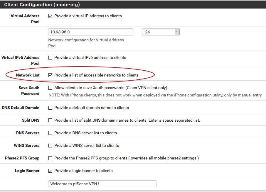
 3.) Mobile client settings at pfSense location "network 2":
Client VPN dialin setting is fully based on this local tutorial which has all the details:IPsec IKEv2 VPN für mobile Benutzer auf der pfSense oder OPNsense Firewall einrichten
Both networks should be provided to the clients.
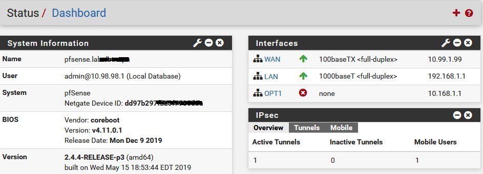
 4.) Dashboard overview at "network 2":
- Tunnel with both P2s established to network 1.
- One active client (Windows 10 with onboard VPN client) connected.
 5.) Connectivity checks on the client:
Optionally you should set a static route into the VPN client connection on the Windows 10 site with Power Shell (Admin mode): Add-VpnConnectionRoute -ConnectionName "pfSense" -DestinationPrefix 192.168.1.0/24 -PassThruand additionally
Add-VpnConnectionRoute -ConnectionName "pfSense" -DestinationPrefix 172.17.1.0/24 -PassThru
This is usually not mandatory cause the pfSense mobile connection setup will provide both configured P2 networks automatically into the client routing table during client tunnel establishment. But Windows is here a bit "sensitive", cause the internal routing table needs administrator rights. So its more waterproof to additionnally add that route into the VPN client setup here to make sure it works under all circumstances.
Checking the client routing table while the client is connected:
C:\WINDOWS> route print
===========================================================================
Schnittstellenliste
 18...00 23 5a 4f 01 55 ......Intel(R) 82567LM Gigabit Network Connection
 38...........................pfSense
  9...00 22 fa 7b c9 c7 ......Intel(R) WiFi Link 5100 AGN
  1...........................Software Loopback Interface 1
===========================================================================

IPv4-Routentabelle
===========================================================================
Aktive Routen:
     Netzwerkziel    Netzwerkmaske          Gateway    Schnittstelle Metrik
          0.0.0.0          0.0.0.0    192.168.178.254    192.168.178.174     55
         10.0.0.0        255.0.0.0   Auf Verbindung        10.98.98.1     36
       10.98.98.1  255.255.255.255   Auf Verbindung        10.98.98.1    291
       10.99.1.99  255.255.255.255    192.168.178.254    192.168.178.174     56
   10.255.255.255  255.255.255.255   Auf Verbindung        10.98.98.1    291
        127.0.0.0        255.0.0.0   Auf Verbindung         127.0.0.1    331
        127.0.0.1  255.255.255.255   Auf Verbindung         127.0.0.1    331
  127.255.255.255  255.255.255.255   Auf Verbindung         127.0.0.1    331
      169.254.0.0      255.255.0.0    192.168.178.165    192.168.178.174     56
       172.17.1.0    255.255.255.0   Auf Verbindung        10.98.98.1     36
     172.17.1.255  255.255.255.255   Auf Verbindung        10.98.98.1    291
      192.168.1.0    255.255.255.0   Auf Verbindung        10.98.98.1     36
192.168.1.255 255.255.255.255 Auf Verbindung 10.98.98.1 291 VPN client has gotten the right IP address (10.98.98.1) from the internal VPN IP which could also be seen in the above routing table:
C:\WINDOWS> ipconfig
Windows-IP-Konfiguration

Ethernet-Adapter LAN-Verbindung:
   Verbindungsspezifisches DNS-Suffix: testing.intern
   Verbindungslokale IPv6-Adresse  . : fe80::f488:debb:2cdf:1234%18
   IPv4-Adresse  . . . . . . . . . . : 192.168.178.100
   Subnetzmaske  . . . . . . . . . . : 255.255.255.0
   Standardgateway . . . . . . . . . : fe80::1:1%18   192.168.178.1

PPP-Adapter pfSense:
   Verbindungsspezifisches DNS-Suffix:
   IPv4-Adresse  . . . . . . . . . . : 10.98.98.1
   Subnetzmaske  . . . . . . . . . . : 255.255.255.255
   Standardgateway . . . . . . . . . :
And finally the Ping check into the local LAN on network 1:
PS C:\WINDOWS> ping 172.17.1.1
Ping wird ausgeführt für 172.17.1.1 mit 32 Bytes Daten:
Antwort von 172.17.1.1: Bytes=32 Zeit=11ms TTL=63
Antwort von 172.17.1.1: Bytes=32 Zeit=8ms TTL=63
Antwort von 172.17.1.1: Bytes=32 Zeit=4ms TTL=63
Antwort von 172.17.1.1: Bytes=32 Zeit=11ms TTL=63

Ping-Statistik für 172.17.1.1:
    Pakete: Gesendet = 4, Empfangen = 4, Verloren = 0
    (0% Verlust),
Ca. Zeitangaben in Millisek.:
Minimum = 4ms, Maximum = 11ms, Mittelwert = 8ms Conclusion:
Works as designed !
And...if it works for you as well, feel free to post or link it to the Netgate forum as well !!
