Mikrotik: mDNS Repeater as Docker-Container on the Router (ARM,ARM64,X86)

Table of contents
mDNS repeating (Multicast DNS) on Mikrotik routers, a feature often requested, is not yet part of RouterOS itself at the time of writing (But Mikrotik is currently working on it). However, since a Docker package for RouterOS 7 has been available for some time, I have built a Docker image based on the template of this Github Repo which runs directly on the router and reflects mDNS multicast packets between two or more VLANs. This enables the cross VLAN announcement of many devices which normally only announce themselves in their own layer-2 broadcast domain using the mDNS link local multicast address 224.0.0.251 via UDP port 5353. The container is based on a small Alpine Linux and the repeating is done by a C programmed daemon from Darell Tan.
I extended the container in the sense that VLANs can be changed easily via an environment variable on the Mikrotik. I also provide a Mikrotik script which automates the complete interface setup and container creation.
In the instructions and the Mikrotik script I assume that you run a current VLAN setup via "VLAN filtering" in a VLAN bridge, like @aqui shows in his instructions Mikrotik VLAN Konfiguration ab RouterOS Version 6.41 on this board.
At the time of writing, the container feature of Mikrotik is limited to these platforms
- ARM
- ARM64
- x86 (z.B. CHR)
That would be the following models (excerpt, without claim to completeness)
- RB3011UiAS-RM
- RB4011iGS+RM
- RB5009UG+S+IN /RB5009UPr+S+IN
- RB1100AHx4
- CCR2004-16G-2S+PC / CCR2004-16G-2S+ / CCR2004-1G-12S+2XS / CCR2116-12G-4S+ / CCR2216-1G-12XS-2XQ / CCR2004-1G-2XS-PCIe
- CRS305-1G-4S+IN / CRS310-1G-5S-4S+IN / CRS326-24G-2S+IN / CRS309-1G-8S+IN / CRS328-4C-20S-4S+RM / CRS317-1G-16S+RM
- netPower 15FR / netPower 16P / FiberBox Plus / netFiber 9
- and any hardware which can run the x86 variant of RouterOS.
RAM: For reasonable operation, a recommend using a router with at least 128MB of RAM.
File-Storage: The container itself uses between 10 -15MB when extracted to the filesystem.
If the own device e.g. only has 16MB Flash but owns a USB port, the root directory of the container can also be placed on it. Furthermore, starting with RouterOS 7.7, it is also possible to create a RAM disk where a part of the main memory can be used as data storage.
help.mikrotik.com/docs/display/ROS/Disks#Disks-AllocateRAMtofold ...
/disk add type=tmpfs tmpfs-max-size=50M slot=myRamDisk
The container package is available since RouterOS v7.4beta4. It is available for download at Mikrotik-Downloads under the topic Extra Package for one of the above mentioned platforms.
From the downloaded ZIP, extract the file container-7.x.npk (the "x" stands for the currently available version) and either drag and drop the file into Winbox or use FTP/SFTP into transfer the file to the root directory of the router.
To complete the installation, it is mandatory to restart the router once. Afterwards, the feature is available in Winbox under Container in the left navigation.

For all those who can't/won't build the container themselves, I have prepared three ready-made container images that you can download here:
(Build date: March 2023)
If you want to build the containers by yourself from source, you will find the sources and instructions for the build process in the last topic of this tutorial.
Now copy the image which suits your platform into the root directory on the router (again via drag n' drop into Winbox or via FTP/SFTP).
For the setup including the necessary interfaces and assignment to the VLAN bridge I wrote a Mikrotik script which does the complete work. It has to be executed once in a terminal window after copying the image to the router. If you prefer to adjust all settings by yourself, you can follow the variant B in the next topic and skip this step.
For the script to fit into your environment, you have to adjust the following variables in the head of the script:
| Variable | Beschreibung |
|---|---|
| BRIDGENAME | Name of the VLAN bridge where the vlans are member of |
| VETHNAME | This will be the name of the VETH interface of the container |
| HOSTNAME | Hostname which will be used by the container |
| VLANS | An array of vlan-ids (seperated by semicolon) |
| IMAGENAME | Filename of the container archive (you copied to the router) |
| CONTAINERROOT | Folder where the filesystem of the container will be extracted |
For the virtual network interface of the container(VETH) I use a subnet which is otherwise not used on the router (172.19.19.0/24), since this is actually not needed for communication in the container, adjust it to a subnet which is not used by your router in the following line of the script:
/interface veth add address=172.19.19.2/24 gateway=172.19.19.1 name=mDNSTrunk
Enter again on the console so that the script block{} is executed.{
# name of bridge to add veth interface to
:local BRIDGENAME "bridgeLocal"
# name the veth interface will get
:local VETHNAME "mDNSTrunk"
# set hostname of container
:local HOSTNAME "mDNS"
# set vlan-ids to reflect traffic between
:local VLANS {100;200}
# define image filename
:local IMAGENAME "mdns_x86.tar"
# path to data root for the container
:local CONTAINERROOT "docker/container/mdns_repeater"
# -------------------------------
# variable holds all vlans seperated by spaces
:local ALLVLANS ""
# check bridge existance
:if ([:len [/interface bridge find name="$BRIDGENAME"]] = 0) do={
:put "Could not find a bridge with name '$BRIDGENAME' !"
:quit
}
# add veth interface
:if ([:len [/interface veth find name="$VETHNAME"]] = 0) do={
# add veth interface
/interface veth add address=172.19.19.2/24 gateway=172.19.19.1 name=$VETHNAME
}
# add veth interface to bridge
:if ([:len [/interface bridge port find interface=$VETHNAME]] = 0) do={
/interface bridge port add interface=$VETHNAME bridge=$BRIDGENAME
}
# for each vlan id
:foreach id in=$VLANS do={
# find existing vlan entry
:local vlanentry [/interface bridge vlan find vlan-ids ~ "(^|;)$id(;|\$)" and bridge=$BRIDGENAME]
:if ([:len $vlanentry] = 0) do={
# if entry does not exist add it to vlan list
/interface bridge vlan add bridge=$BRIDGENAME tagged="$BRIDGENAME,$VETHNAME" vlan-ids=$id
} else={
# if entry exists and veth interface is not a tagged member append veth interface to vlan as tagged interface
:if ([:len [/interface bridge vlan find vlan-ids=$id and current-tagged ~ "$VETHNAME"]] = 0) do={
/interface bridge vlan set $vlanentry tagged=([get $vlanentry tagged],"$VETHNAME")
}
}
# build ALLVLAN variable
:if ($ALLVLANS != "") do={
:set ALLVLANS ($ALLVLANS . " " . $id)
} else={
:set ALLVLANS $id
}
}
# add container environment variable wich defines the vlans used
:if ([:len [/container envs find name=mdns key=VLANS]] = 0) do={
/container envs add name=mdns key=VLANS value=$ALLVLANS
}
# finally add container
:if ([:len [/container find root-dir="$CONTAINERROOT"]] = 0) do={
/container add file=$IMAGENAME envlist=mdns logging=yes start-on-boot=yes root-dir="$CONTAINERROOT" interface=$VETHNAME hostname=$HOSTNAME
} else={
:put "Container already exists, please delete it beforehand and run again!"
}
}Using Winbox:
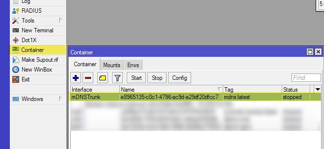
Oder via terminal:
/container print
Furthermore, a container environment variable named VLANS should have been created in which the above VLAN-IDs are separated from each other with spaces:
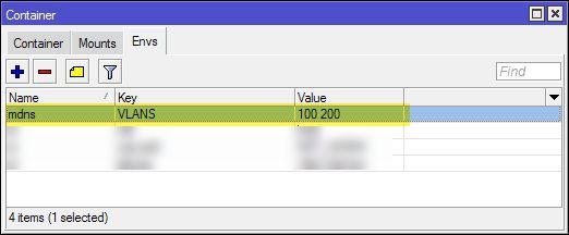
This variable determines the VLAN-IDs which are interconnected via mDNS after the start of the container, so if you want to change the VLANs afterwards, you are doing this here. If you change the IDs here, the VETH interface must of course be manually added as a tagged interface under
/interface bridge vlan in the respective VLAN. The container has to be restarted after a change.For the manual setup, I will show the necessary steps in the following Winbox screenshots.
First we will need to create a new virtual network interface for the containter (VETH):
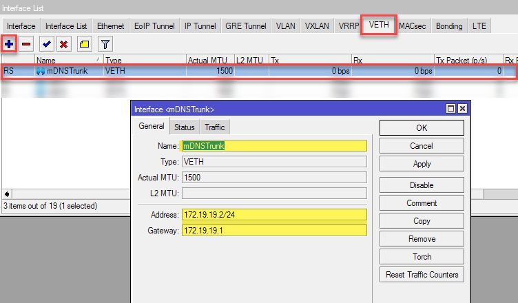
The subnet specified here (172.19.19.0/24) must be an unused address range on the router. Effectively this network will not be used in the container because the communication takes place exclusively via the VLAN tagged connections, so it can be adjusted freely.
Now we will add this interface as a member port of our VLAN bridge:

Under Bridge >VLANs add the VETH interface as
tagged to your VLAN-IDs
Now we switch to Container > Envs section in Winbox and add a container environment variable for the used VLANs. The VLAN-IDs have to be separated from each other with spaces.
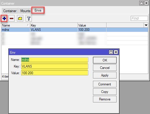
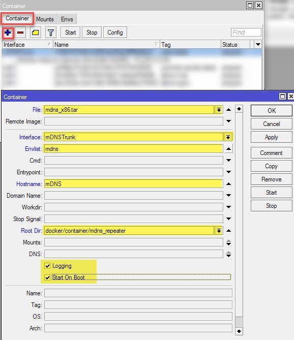
Finally we create the container specifying the archive previously copied to the router, the VETH interface, the environment variable created, and the folder into which the image of the container will be extracted.
Now we are ready to start the container. Select it in Winbox and click on Start:
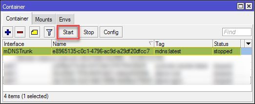
Or use the terminal (replace the 0 with the number displayed at the start of the line)
/container print
start 0
To see what's going on, open a log window and watch the debug output of the container. If the start was successful, it should look like this. (In the example, VLANs 100 and 200 are connected to the container.)
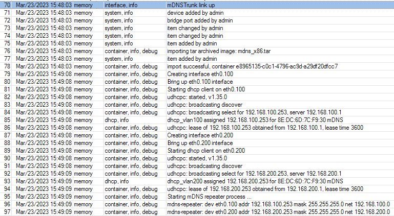
You can see that for each VLAN ID a corresponding VLAN interface is created inside the container. uDHCP acquires IP addresses via DHCP in these VLANs and finally starts the repeating process.
For debugging purposes, the terminal can be used to start a shell within the container. To do this, we open a terminal, list the containers, and then start the shell by specifying the listed number
/container print
shell 0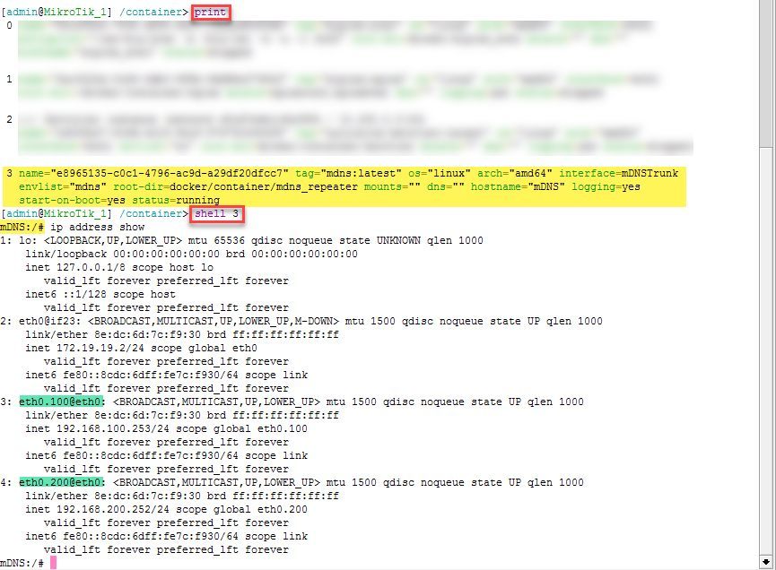
Here you can see the active processes (repeater process and DHCP daemons) and the mDNS listeners on the VLAN interfaces inside the container.

To exit the shell, press
STRG+D.If the setup was successful and devices in each vlan can see each other, this was only the first step, since only the mDNS packets are flooded into the participating VLANs. Since most users use the firewall to separate the VLANs, traffic between the desired devices must first be allowed when blocked by default.
Because everyone's firewall rules are set up differently, I can only provide some recipes that you can adapt to your needs. If you run a statefull firewall configuration with "related/established" rules, which I assume, the rule has to be created only from the side of connection initiation.
Example A: Allow user with IP 192.168.100.50 in VLAN100 to port 80 of a device with IP 192.168.200.60 in VLAN200.
/ip firewall filter add chain=forward place-before=0 src-address=192.168.100.50 dst-address=192.168.200.60 in-interface=vlan100 out-interface=vlan200 protocol=tcp dst-port=80 action=accept
/ip firewall filter add chain=forward place-before=0 src-address=192.168.100.50 dst-address=192.168.200.0/24 in-interface=vlan100 out-interface=vlan200 action=accept
For those of you who want to build the container yourself, I prepared a tar archive you can download here:
mDNS container source
To build the container images, an installation of Docker with the "dockerx" extension is required.
For installing Docker, follow the guide for your distribution => Install Docker Engine.
The archive contains a script that helps building the desired platform image. The platform should be the first parameter (Valid platforms: x86, arm, arm64).
sudo ./build_image.sh x86
sudo docker run --privileged --rm docker/binfmt:a7996909642ee92942dcd6cff44b9b95f08dad64
Hope this tutorial helps you achieve your goals.
Regards @colinardo
Bitte markiere auch die Kommentare, die zur Lösung des Beitrags beigetragen haben
Content-ID: 6541421462
Url: https://administrator.de/tutorial/mikrotik-mdns-repeater-as-docker-container-on-the-router-arm-arm64-x86-6541421462.html
Ausgedruckt am: 14.07.2025 um 07:07 Uhr
1 Kommentar
Serie: Mikrotik Docker Container
NPS 802.1x Radius Authentication with EAP-TLS and strong certificate mapping for non domain joined devices (englisch)1Mikrotik: mDNS Repeater as Docker-Container on the Router (ARM,ARM64,X86) (englisch)1Mikrotik: mDNS Repeater als Docker-Container auf dem Router (ARM,ARM64,X86)16