Cisco, Mikrotik, pfSense site-to-site VPN with dynamic routing

Table of contents
The following tutorial is an addon to existing VPN tutorials on administrator.de. It describes a mixed hardware VPN site-to-site setup between Cisco and Mikrotik routers on IPsec basis.
It covers a design with a powerful VPN core device in the headquarter location and small remote locations equiped with Mikrotik due to budgetary reasons.
The highlight here is the secure IPsec connection which on top carries a GRE overlay tunnel. This allows multicast based dynamic routing protocols like RIPv2 or OSPF as well as native multicast Traffic to be carried over secure VPN links.
Dynamic routing protocols ease the routing management and avoid typical config mistakes maked by managing large amounts of static routes in each device.
With a large number of remote locations also dynamic backup of VPN links can easily be achieved and hence makes the whole network more reliable in terms of possible link or provider faulure. Especially in remote locations which demand higher avalability due to e.g. a central Voice PBX, cashier systems etc. a quick and automatic backup can be a major pluspoint to mitigate connection problems and keep centralized applications online.
This also brings native multicast routing and the option to stream audio and video data resources very efficient into remote locations.
The shown screenshots in this guide can be used for own projects and have to be set to local IP adressing schemes.
The examples do show setups for Cisco or Mikrotik installations and in the second part includes open source firewalls pfSense and OPNsense.
Its a blueprint as well for networks with a single vendor like Cisco or Mikrotik only and also applies to the choice of the dynamic routing protocols. OSPF is more flexible, has a quicker convergence and less overhead. RIPv2 is easier in terms of configuration, requires no planning and is very often part of the featureset in cheap layer 3 switches.
The advanced link connection at the bottom shows additional links who also cover basics and other threads relating to the topics of this tutorial.
The configuration is quite easy and can also be done by network beginners with basic knowledge of the Cisco command line and Mikrotiks WinBox tool. Basic IP protocol knowledge will be helpful as well.
The Internet is simulated here by several 10.x IP networks. All VPN routers work in a classical NAT router configuration with their WAN / Internet port connected via NAT (network address translation) and a firewall in a typical Internet design and a local LAN under real conditions.
VPN encryption is done in common AES 256.
The VPN test design can be seen here:

First step shows the basic setup of both routers. This setup use the following IP addressing:
Internet address Cisco = 10.99.1.198
Internet address Mikrotik = 10.1.1.150
GRE tunnel network = 172.31.31.8 /30 (Cisco=172.31.31.9, Mikrotik=172.31.31.10)
Local LAN networks according to the above picture.
The tunnel network is designed in a point to point network hence a 30 bit prefix (255.255.255.252 mask) with two addressable hosts is used.
Second step shows the corresponding Mikrotik setup and in an advanced chapter the number of local LANs will be increased with the setup to a more realistic setup.
Let's start....
The tutorial did not cover a standard Internet setup in detail to not blow up this tutorial. This can be seen in the Cisco_basic_setup_tutorial described here in the forum. It is valid for all other Cisco router models as well and partially also for IOS based L3 switches.
The tutorial covers only the VPN, GRE and firewall relevant commands. Firewall is on the basis of Cisco's modern ZBF (Zone Based Firewall) concept in IOS.
(All red marked config parameters are related to the advanced design with multiple locations and networks described in chapter 6. All comments regarding the configuration itself are printed in black.)
!
hostname cisco_router
!
aaa new-model
!
aaa authentication login default local
aaa authorization network default local
!
clock timezone CET 1 0 ==> Clock set to Europe and summertime
clock summer-time CEST recurring last Sun Mar 2:00 last Sun Oct 3:00
!
ip dhcp binding cleanup interval 30
ip dhcp excluded-address 192.168.77.1 192.168.77.100 ==> DHCP IP addresspool .101 bis .149
ip dhcp excluded-address 192.168.77.150 192.168.77.254
!
ip dhcp pool LAN ==> DHCP server for local LAN
network 192.168.77.0 255.255.255.0
dns-server 192.168.7.254
domain-name cisco.home.arpa
default-router 192.168.77.1
!
ip domain lookup source-interface Ethernet1
ip domain name cisco.home.arpa
ip name-server <DNS IP-Adresse>
ip inspect log drop-pkt ==> Logging of dropped pakets from the firewall
!
class-map type inspect match-any internet-allowed ==> Setup of allowed pakets through the firewall
description Allow Internet access
match access-group name WAN_IN
class-map type inspect match-any lan-allowed ==> Setup of allowed pakets through the firewall
description Allow local protocols to Internet
match protocol dns
match protocol http
match protocol https
match protocol imaps
match protocol smtp extended
match protocol sip-tls
match protocol rtsp
match protocol ssh
match protocol ntp
match protocol tcp
match protocol udp
match protocol icmp
!
policy-map type inspect lan-allowed-policy ==> Firewall policy local LAN to Internet
description LAN to Internet policy
class type inspect lan-allowed
inspect
class class-default
drop
policy-map type inspect internet-allowed-policy ==> Firewall policy Internet to router
description Internet to router policy
class type inspect internet-allowed
pass
class class-default
drop
!
zone security lan
zone security wan
zone-pair security lan-wan source lan destination wan
description Firewall LAN-Internet
service-policy type inspect lan-allowed-policy
zone-pair security wan-self source wan destination self
description Firewall Internet-Router
service-policy type inspect internet-allowed-policy
!
crypto keyring MTVPN
pre-shared-key address 10.1.1.150 key test123
pre-shared-key address 10.99.1.149 key geheim123 ==> Second VPN router (See: chapter 6)
!
crypto isakmp policy 10 ==> Setup IPsec cipher suite
encr aes 256
hash sha256
authentication pre-share
group 14
!
crypto isakmp profile Mikrotik-1 ==> Connection parameter Mikrotik-1
description IPsec Mikrotik-1
keyring MTVPN
match identity address 10.99.1.149 255.255.255.255
crypto isakmp profile Mikrotik-2 ==> Connection parameter Mikrotik-2 (See: chapter 6)
description IPsec Mikrotik-2
keyring MTVPN
match identity address 10.1.1.150 255.255.255.255
!
crypto ipsec transform-set mikrotik esp-aes 256 esp-sha256-hmac
mode transport ==> IPsec transport mode for GRE tunnel !
!
crypto map mikrotik 10 ipsec-isakmp ==> Router Mikrotik-2 (See: chapter 6)
description IPsec Mikrotik-2
set peer 10.1.1.150
set transform-set mikrotik
set isakmp-profile Mikrotik-2
match address 107 ==> All defined by this ACL goes encrypted into the tunnel
crypto map mikrotik 15 ipsec-isakmp
description IPsec Mikrotik-1
set peer 10.99.1.149
set transform-set mikrotik
set isakmp-profile Mikrotik-1
match address 108
!
interface Tunnel0 ==> GRE tunnel interface
description GRE zu Mikrotik-2
ip address 172.31.31.9 255.255.255.252
ip mtu 1400
zone-member security lan
tunnel source 10.99.1.198
tunnel destination 10.1.1.150
tunnel path-mtu-discovery
!
interface Tunnel1
description GRE zu Mikrotik-1
ip address 172.31.31.1 255.255.255.252
ip mtu 1400
zone-member security lan
tunnel source 10.99.1.198
tunnel destination 10.99.1.149
tunnel path-mtu-discovery
!
interface Vlan1
description Local LAN
ip address 192.168.77.1 255.255.255.0
ip nat inside
ip virtual-reassembly in
zone-member security lan
!
interface Vlan10
description Local VLAN-10
ip address 192.168.177.1 255.255.255.0
ip nat inside
ip virtual-reassembly in
zone-member security lan
!
interface Ethernet 1
description Internet / WAN connection
ip address 10.99.1.198 255.255.255.0
no ip redirects
no ip unreachables
ip nat outside
zone-member security wan
crypto map mikrotik
!
router rip ==> Dynamic RIP Routing with version 2 !
version 2
passive-interface default
no passive-interface Tunnel0
no passive-interface Tunnel1
network 172.31.0.0 ==> Networks in classical notation
network 192.168.77.0
network 192.168.177.0
no auto-summary ==> Activation of CIDR masks
!
ip route 0.0.0.0 0.0.0.0 10.99.1.254 ==> Default route Internet
!
ip dns server ==> Cisco is DNS Proxy. (Remove when using local DNS server !)
ip nat inside source list 101 interface Ethernet 1 overload
!
ip access-list extended WAN_IN
permit icmp any any echo-reply
permit icmp any any packet-too-big
permit icmp any any time-exceeded
permit udp any eq bootps any
permit udp any any eq isakmp
permit udp any any eq non500-isakmp
permit esp any any
permit gre any any
permit udp any eq domain any
permit tcp any eq domain any
permit udp any eq ntp any
!
access-list 101 deny ip 192.168.77.0 0.0.0.255 172.16.0.0 0.15.255.255 ==> Exclude local VPN Traffic (Tunnel) from NAT
access-list 101 deny ip 192.168.77.0 0.0.0.255 192.168.0.0 0.0.255.255
access-list 101 deny ip 192.168.177.0 0.0.0.255 172.16.0.0 0.15.255.255 ==> Exclude local VLAN 10 Traffic (Tunnel) from NAT (Tunnel)
access-list 101 deny ip 192.168.177.0 0.0.0.255 192.168.0.0 0.0.255.255
access-list 101 permit ip 192.168.77.0 0.0.0.255 any Everything else via NAT to Internet
access-list 101 permit ip 192.168.177.0 0.0.0.255 any Same with VLAN-10
access-list 107 permit gre host 10.99.1.198 host 10.1.1.150 ==> Encrypt GRE traffic (IP 47) to Mikrotik-2 IPsec ##
access-list 108 permit gre host 10.99.1.198 host 10.99.1.149 ==> Encrypt GRE traffic (IP 47) to Mikrotik-1 IPsec ##
!
ntp server ntps1-0.cs.tu-berlin.de source Ethernet 1 ==> Router clock setup via NTP (Reference TU Berlin)
!
end
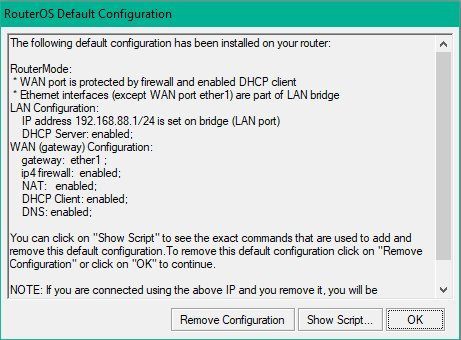
On Mikrotik Router platforms the standard default configuration can be used. This default setup sets the router in a classical default router configuration where ether 1 is the WAN / Internet port including a waterproof firewall and NAT (IP address translation) setup and works as a DHCP Client on the WAN port. The WAN port gets an IP automatically when placed in an existing network with DHCP address distribution.
The default config provides a ready configured waterproof firewall setup on ether1 port as mentioned before. This prevents beginners from possible errors with a manual setup and assures a safe protection.
It can be activated on reboot via the Mikrotik main menue "System -> Reset Configuration" and checking "Default Configuration" and "No Backup" to start this factory reset with the described default setup.
Default configuration
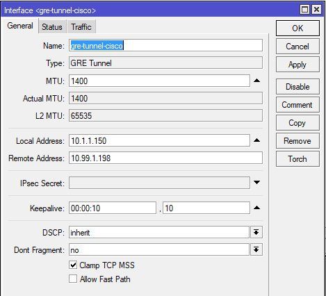
First step is to setup a tunnel interface in the Interfaces - GRE menue.
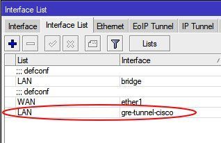
Tunnel interface setup and adding to "LAN" interface list:
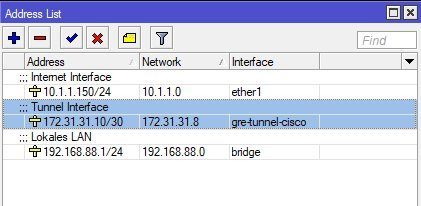
IP address setup on all interfaces:
Mikrotik offers the option to setup a separate IPsec policy profile for phase 1 and 2. When in need this can be done.
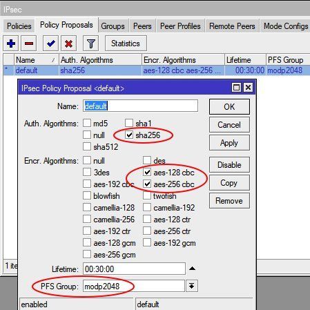
For beginners its much easier and recommended to use the existing default profiles and get rid of unsecure settings (3DES, SHA1 and MD5) in these profiles and only use the modern and trustful AES encryption with SHA256 hashing and DH group 14. These so "cleaned" default profiles can then be used for a quicker setup.
IPsec peer profile (Phase 1) setup
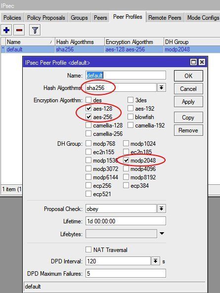
IPsec policy profile (Phase 2) setup
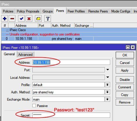
Configuring IPsec peer to Cisco
IPsec peer policies setup
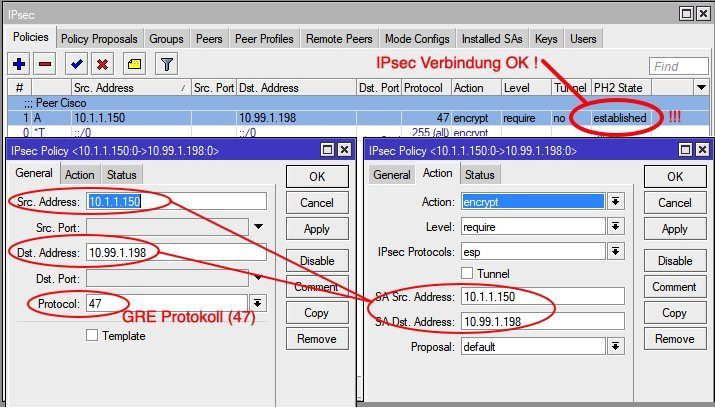
If the IPsec phase 2 status changed here to "Established" the IPsec connection is OK and the tunnel is active. The Cisco router on the other end will then show with show crypto isakmp sa the QM_IDLE state.
cisco_router#sh crypto isakmp sa
IPv4 Crypto ISAKMP SA
dst             src             state          conn-id status
10.99.1.198     10.1.1.150      QM_IDLE           2002 ACTIVE
10.1.1.150 10.99.1.198 QM_IDLE 2001 ACTIVE In general every dynamic routing protocol can be used here. A distance vector protocol like OSPF is always an option here if needed or preferred.
To keep this first setup a bit easier, also in terms of overview, RIPv2 is used here in a first step. An OSPF setup can be seen in the advanced chapter at the bottom covering also modern VTI interfaces.
RIP can be found as a feature in most SoHo router models or L3 switches and is also available in a number of firewalls.
Most important is to ALWAYS use version 2 of the RIP protocol !!!
Only RIPv2 can handle classless CIDR_subnetmasks. Today all networks are classless and RFC 1518 / 1519 defines this since 1993.
RIPv2 activation om Mikrotik and local network setup:
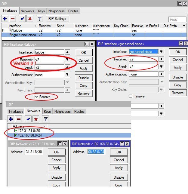
This needs to be changed and removed of course if local RIP routers are also present in local LANs !
Its also possible to set passwords on both ends to protect intruders from injecting fake routes into the network and adding more security.
Routing table and IP connection check

Distance : 0=Local, 1=Static, 120=learned with RIPv2)
Routing Tabellen Check auf dem Cisco Router:
cisco_router#sh ip rou
Codes: L - local, C - connected, S - static, R - RIP, M - mobile, B - BGP
       D - EIGRP, EX - EIGRP external, O - OSPF, IA - OSPF inter area
       N1 - OSPF NSSA external type 1, N2 - OSPF NSSA external type 2
       E1 - OSPF external type 1, E2 - OSPF external type 2
       i - IS-IS, su - IS-IS summary, L1 - IS-IS level-1, L2 - IS-IS level-2
       ia - IS-IS inter area, * - candidate default, U - per-user static route
       o - ODR, P - periodic downloaded static route, H - NHRP, l - LISP
       a - application route
       + - replicated route, % - next hop override, p - overrides from PfR

Gateway of last resort is 10.99.1.254 to network 0.0.0.0

S*    0.0.0.0/0 [254/0] via 10.99.1.254
      10.0.0.0/8 is variably subnetted, 2 subnets, 2 masks
C        10.99.1.0/24 is directly connected, Ethernet1
L        10.99.1.198/32 is directly connected, Ethernet1
      172.31.0.0/16 is variably subnetted, 2 subnets, 2 masks
C        172.31.31.8/30 is directly connected, Tunnel0
L        172.31.31.9/32 is directly connected, Tunnel0
      192.168.77.0/24 is variably subnetted, 2 subnets, 2 masks
C        192.168.77.0/24 is directly connected, Vlan1
L        192.168.77.1/32 is directly connected, Vlan1
R     192.168.88.0/24 [120/1] via 172.31.31.10, 00:00:01, Tunnel0

cisco-router#sh ip rip database
172.31.0.0/16    auto-summary
172.31.31.8/30    directly connected, Tunnel0
192.168.77.0/24    auto-summary
192.168.77.0/24    directly connected, Vlan1
192.168.88.0/24    auto-summary
192.168.88.0/24
[1] via 172.31.31.10, 00:00:19, Tunnel0 A Ping from the local LAN into the remote local LAN is verifying now the working tunnel connection.
Trusting is nice but a check is better... !
What about configuration errors and security ? Are all data encryted and secure ?
Some doubts always remain more or less if it comes down to security and its better to make sure everything is really waterproof.
Therefor a quick checkup is never a waste of time if sensitive data runs over public networks. It gives higher trust in VPN solutions like these.
The Cisco router shows his security with:
cisco_router#sh crypto isakmp policy
Global IKE policy
Protection suite of priority 10
        encryption algorithm:   AES - Advanced Encryption Standard (256 bit keys).
        hash algorithm:         Secure Hash Standard 2 (256 bit)
        authentication method:  Pre-Shared Key
        Diffie-Hellman group:   #14 (2048 bit)
lifetime: 86400 seconds, no volume limit 
At the end a Wireshark sniffer trace wipes away all further doubts:
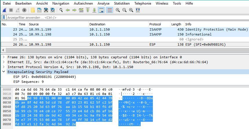
Waterproof and works as designed...! 👍
A more real live related setup is one with multiple local LAN segements, cause the majority of company networks, no matter if small or big, are segmented those days. Due to legal and security issues voice VLANs and guest WLANs (as an example) have to be separated from the company's own network. This results in the simple fact that actual networks have always a minimum of 3 segments.
The following example shows three locations and can easily be extended to more locations. Config steps are always the same.
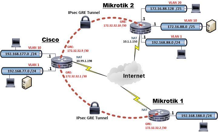
The additional Cisco router config steps which are needed for a second location and an additional VLAN (10) can be seen red marked in the above shown Cisco router configs.
The forum has a detailed VLAN basic guide as a help for setting up VLANs on a Mikrotik. This guide can be found HERE !
The only additional config step on the Mikrotik is to add RIPv2 support and setup the local IP nets for RIP routing.
A very interesting alternative to GRE tunnels is the use of modern VTI interfaces. The majority of products do support VTIs in connection with IPsec encryption today. VTIs do make the VPN config a bit slicker than GRE setups. The benefit is that VTI interfaces can be treated as normal LAN interfaces in a configuration which makes the setup and management a lot easier for the admin.
This demo setup is using the same setup as described above. The only difference is that we will change to the more sophisticated OSPF protocol instead of RIPv2 to show both protocol options in real live.
pfSense or OPNsense needs with the Quagga-OSPF package or alternatively the FRR package to support OSPF. Which one is a question of personal taste. The example config here uses FRR. Both packages are more or less identical from a function perspective.
Mikrotik has actually no support for VTI. This will most likely come in further firmware editions hence the setup is done so far with pfSense or OPNsense and Cisco as an example. Also in terms of overview the tutorial shows only the changed setup commands in the Cisco config.
Lets start again...
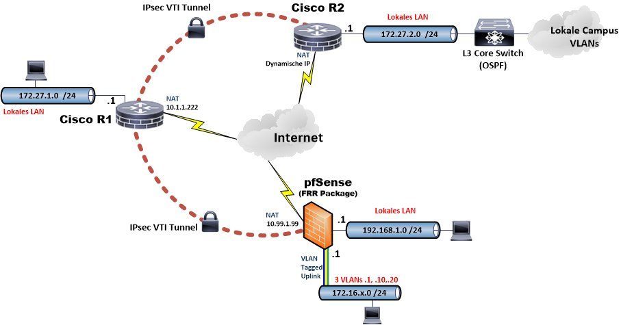
Cisco Router 1 (R1):
!
crypto keyring ROUTER1
pre-shared-key address 0.0.0.0 0.0.0.0 key geheim123
pre-shared-key hostname CiscoR2 key geheim1234
!
crypto isakmp policy 5
encr aes 256
hash sha256
authentication pre-share
group 14
!
crypto isakmp policy 10
encr aes
authentication pre-share
group 2
!
crypto isakmp profile DVTI
description Dynamic VPN tunnel
keyring ROUTER1
match identity address 0.0.0.0
virtual-template 3
crypto isakmp profile CISCO_R2
description Dynamic VPN tunnel Cisco R2
keyring ROUTER1
self-identity user-fqdn CiscoR1
match identity user-fqdn CiscoR2
virtual-template 2
!
crypto ipsec transform-set VTISET esp-aes esp-sha-hmac
mode tunnel
!
crypto ipsec profile CISCO_R2
set transform-set VTISET
set isakmp-profile CISCO_R2
!
crypto ipsec profile DVTI
set transform-set VTISET
set isakmp-profile DVTI
!
interface Loopback1
ip address 172.27.27.1 255.255.255.255
!
interface Virtual-Template2 type tunnel
description Tunnel interface Cisco-R2
ip unnumbered Loopback1
ip ospf network point-to-point
tunnel source 10.1.1.222
tunnel mode ipsec ipv4
tunnel destination dynamic
tunnel protection ipsec profile CISCO_R2
!
interface Virtual-Template3 type tunnel
description Dynamic VTI tunnel
ip unnumbered Loopback1
ip mtu 1400 <== (must be mandatory set to 1400 for pfSense to prevent OSPF Link MTU mismatch errors !)
ip ospf network point-to-point
tunnel source 10.1.1.222
tunnel mode ipsec ipv4
tunnel destination dynamic
tunnel protection ipsec profile DVTI
!
interface Vlan1
description Local LAN
ip address 172.27.1.254 255.255.255.0
ip nat inside
!
interface <WAN>
description Internet port
ip address 10.1.1.222 255.255.255.0
ip nat outside
!
router ospf 1
router-id 172.27.27.1
passive-interface default
no passive-interface Virtual-Template2
no passive-interface Virtual-Template3
network 172.27.1.0 0.0.0.255 area 0
network 172.27.27.1 0.0.0.0 area 0
!
end
Cisco Router 2 (R2):
!
crypto keyring ROUTER2
pre-shared-key hostname CiscoR1 key geheim1234
!
crypto isakmp policy 5
encr aes 256
hash sha256
authentication pre-share
group 14
!
crypto isakmp policy 10
encr aes
authentication pre-share
group 2
!
crypto isakmp profile ROUTER1
description IPsec Tunnel Router-1
keyring ROUTER2
self-identity user-fqdn CiscoR2
match identity user-fqdn CiscoR1
!
crypto ipsec transform-set VTISET esp-aes esp-sha-hmac
mode tunnel
!
crypto ipsec profile ROUTER1
set transform-set VTISET
set isakmp-profile ROUTER1
!
!
interface Loopback1
ip address 172.27.27.5 255.255.255.255
!
interface Tunnel1
description VPN Tunnel Router-1
ip unnumbered Loopback1
tunnel source <WAN Interface>
tunnel mode ipsec ipv4
tunnel destination 10.1.1.222
tunnel protection ipsec profile ROUTER1
!
interface <WAN>
description Internet Port
ip address <Dynamic>
ip nat outside
!
interface Vlan1
description Local LAN
ip address 172.27.2.254 255.255.255.0
ip nat inside
!
router ospf 1
router-id 172.27.27.5
passive-interface default
no passive-interface Tunnel1
no passive-interface Vlan1
network 172.27.2.0 0.0.0.255 area 0
network 172.27.27.5 0.0.0.0 area 0
!
end
pfSense or OPNsense use the standard setup here which is not covered in detail. (See advanced links for a basic tutorial)
The pfsense local OPT LAN port is additionally connected tagged to a local VLAN switch serving 3 Vlans 1, 10 und 20 to beef up the OSPF routing table a bit with entries.
Setup starts in the IPsec menue in configuring the standard steps for IPsec phase 1 and phase 2 tunnel settings:
Phase 1:
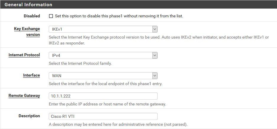
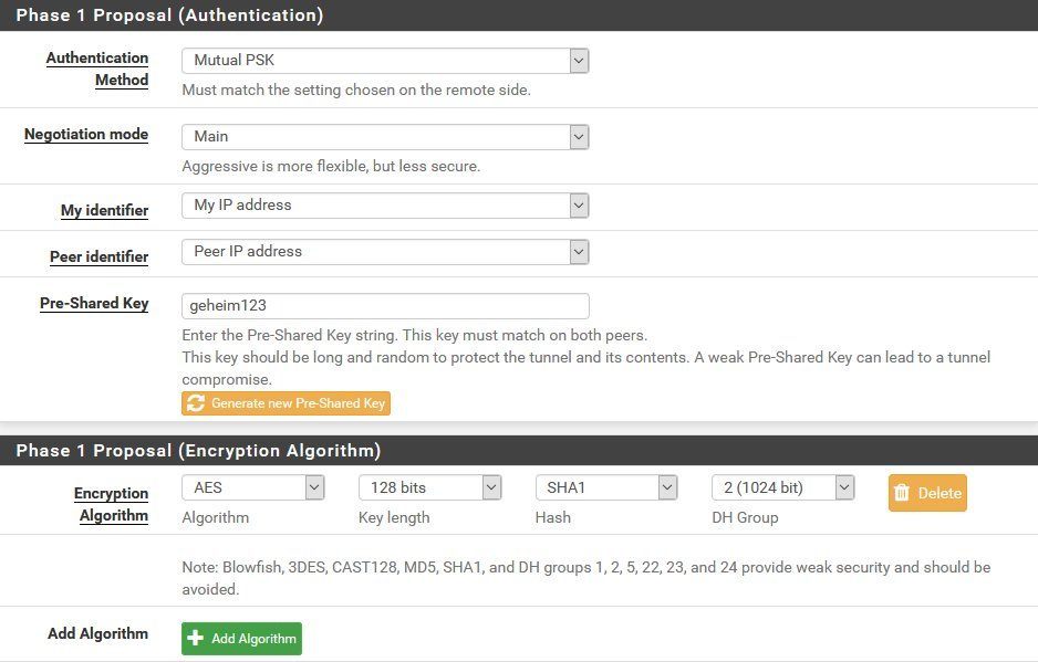
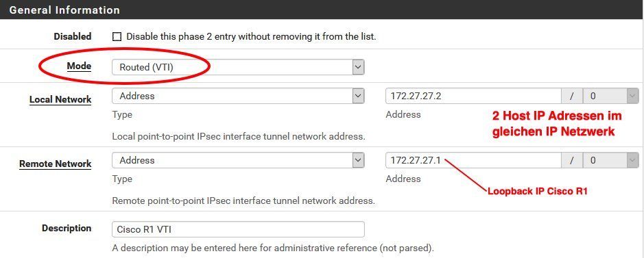
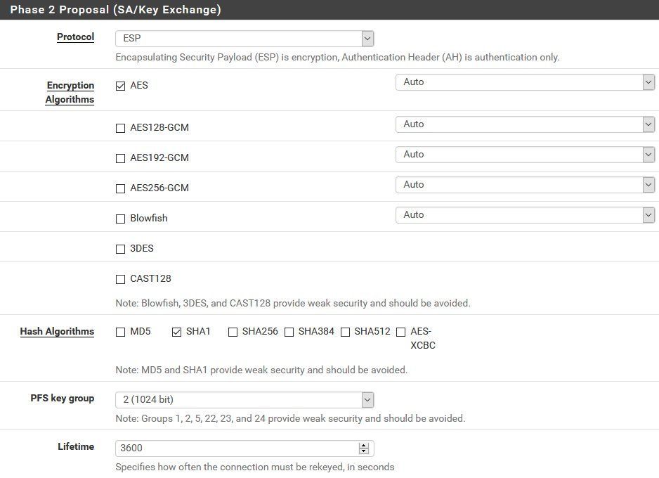
Phase 2:
ATTENTION: Make sure the phase 2 mode is set to (Routed) VTI here !
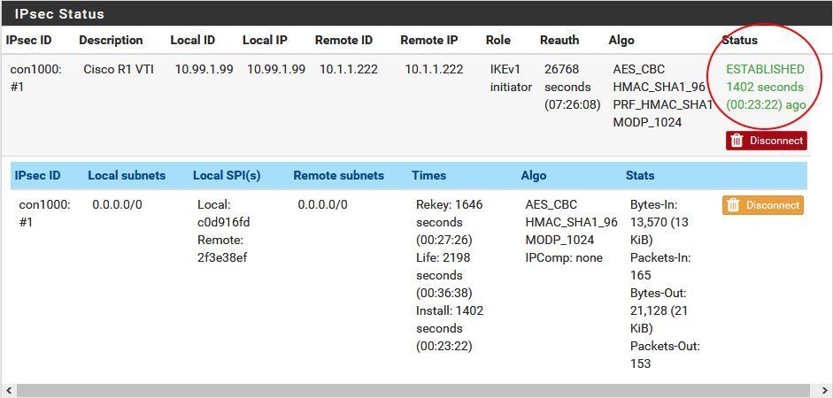
If all went well the IPsec overview looks like this:

In case all config parameters are correct the VTI tunnel to the Cisco will instantly come up and shows the "Established" state.
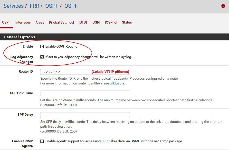
At first the Quagga-OSPF or FRR package has to be installed via the package manager to activate OSPF routing. As mentioned before GUI setups for OSPF a more or less identical in both packages and its a question of taste which one to use. FRR will be used here.
General OSPF activation with logging
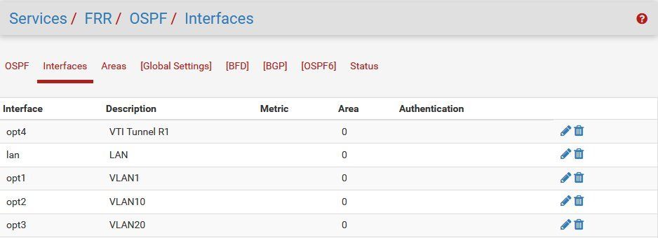
Assigning interfaces to a OSPF area:
(To make the setup easy all interfaces in the example will be placed in the standard area 0)
Cisco R1:
Router-1#show ip ospf neighbor

Neighbor ID     Pri   State           Dead Time   Address         Interface
172.27.27.5       0   FULL/  -        00:00:37    172.27.27.5     Virtual-Access2
172.27.27.2       0   FULL/  -        00:00:35    172.27.27.2     Virtual-Access1

 Router-1#sh ip routes
Codes: L - local, C - connected, S - static, R - RIP, M - mobile, B - BGP
       D - EIGRP, EX - EIGRP external, O - OSPF, IA - OSPF inter area
       N1 - OSPF NSSA external type 1, N2 - OSPF NSSA external type 2
       E1 - OSPF external type 1, E2 - OSPF external type 2
       i - IS-IS, su - IS-IS summary, L1 - IS-IS level-1, L2 - IS-IS level-2
       ia - IS-IS inter area, * - candidate default, U - per-user static route
       o - ODR, P - periodic downloaded static route, H - NHRP, l - LISP
       a - application route
       + - replicated route, % - next hop override, p - overrides from PfR

Gateway of last resort is 10.1.1.254 to network 0.0.0.0

S*    0.0.0.0/0 [1/0] via 10.1.1.254
      10.0.0.0/8 is variably subnetted, 2 subnets, 2 masks
C        10.1.1.0/24 is directly connected, Vlan99
L        10.1.1.222/32 is directly connected, Vlan99
      172.16.0.0/24 is subnetted, 3 subnets
O        172.16.1.0 [110/1100] via 172.27.27.2, 00:07:14, Virtual-Access1
O        172.16.10.0 [110/1100] via 172.27.27.2, 00:07:14, Virtual-Access1
O        172.16.20.0 [110/1100] via 172.27.27.2, 00:07:14, Virtual-Access1
      172.27.0.0/16 is variably subnetted, 5 subnets, 2 masks
C        172.27.1.0/24 is directly connected, Vlan1
L        172.27.1.254/32 is directly connected, Vlan1
O        172.27.2.0/24 [110/1001] via 172.27.27.5, 00:07:27, Virtual-Access2
C        172.27.27.1/32 is directly connected, Loopback1
O        172.27.27.5/32 [110/1001] via 172.27.27.5, 00:07:27, Virtual-Access2
O 192.168.1.0/24 [110/1100] via 172.27.27.2, 00:07:14, Virtual-Access1 The same command shows this on router R2 too.
On pfSense or OPNsense GUI it can be seen via a mouseclick under OSPF status:
Neighbor:

OSPF routing table:
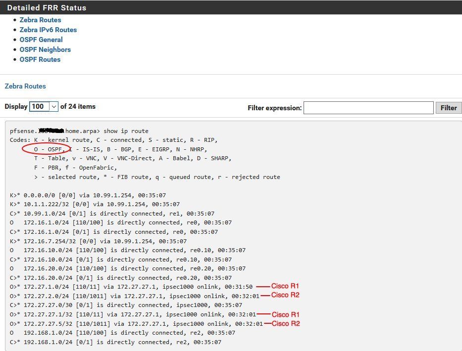
Last but not least the firewall routing table:
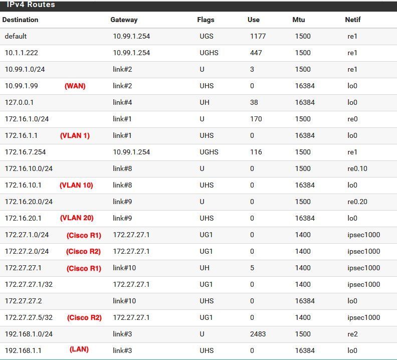
A Ping check to all local LAN interfaces will show that the tunnel and dynmaic routing is "up and running" and the VTI setup works as designed.
Generally there are no obstacles for popular SSH terminal programs under Windows like PuTTY or TeraTerm to access Cisco devices. Linux can be sometimes tricky here, cause of very strong key exchange algorithms in OpenSSH which in most cases do not support diffie-hellman-group14-sha1 used in Cisco and other vendors devices.
To get rid of this, OpenSSH needs some little customization.
In case acces is denied due to non a supported kex algorithm on both ends the ssh command can be extended like this
ssh -oKexAlgorithms=+diffie-hellman-group14-sha1 admin@<ip_address>
Or, to make it permantly a simple text file called "config" can be placed under /home/user/.ssh/ with the following content:
Host 172.30.0.102
KexAlgorithms +diffie-hellman-group14-sha1 Same kex error can occur when trying to SSH access a Linux server from a Cisco device. In this case just add a config text file in the /etc/ssh/sshd_config.d directory like cisco.conf with teh following content:
KexAlgorithms +diffie-hellman-group14-sha1Cisco router basic configuration:
Cisco 800, 900, ISR1100 Router Konfiguration mit xDSL, Kabel, FTTH Anschluss und VPN
RIP protocol overview:
de.wikipedia.org/wiki/Routing_Information_Protocol
cisco.com/c/en/us/td/docs/ios-xml/ios/iproute_rip/configuration/ ...
wiki.mikrotik.com/wiki/Manual:Routing/RIP
Dynamic OSPF Routing with WireGuard:
Merkzettel: VPN Installation mit Wireguard
OSPF with Mikrotik and pfSense/OPNsense via GRE:
aspel.github.io/2018-11-19/ospf-over-gre-tunnel-with-ipsec-mikro ...
Simple IPsec tunnel config with pfSense firewall (no dyn. routing !):
IPSec Site to Site zwischen opnSense und RouterOS mit dynamischen WAN-IP Adressen
Site-to-Site VPN with VTI and Cisco routers only:
Cisco SVTI - Tunnel
Site-to-Site VPN with VTI, Cisco and pfSense/OPNsense firewall:
2921 Kaskadierung mit Fritzbox für IPSEC-Tunnel
IPv6 over IPv4 routing over GRE tunnel interface with OSPF (Cisco):
IPv6 über Cisco IPv4 IPsec Tunnel
Dynamic routing with BGP over Wireguard VPN:
Wireguard BGP routing
Cisco ZFW firewall secured VPNs with Mikrotik and AVM FritzBox:
Cisco IPsec VPN with Mikrotik or FritzBox
Classical Cisco IKEv1 Site-to-Site VPN to pfSense firewall:
2921 Kaskadierung mit Fritzbox für IPSEC-Tunnel
Heterogenous IPsec VPN Site-to-Site VPN with different hardware vendors:
IPsec VPN Praxis mit Standort Vernetzung Cisco, Mikrotik, pfSense, FritzBox u.a
Site-to-Site VPN with pfSense firewall and Mikrotik routers using dynamic IPs:
Hilfe bei OpenVPN Standortvernetzung zwischen pfSense (Server) und Mikrotik (Client)
Mikrotik L2TP VPN for mobile clients:
Scheitern am IPsec VPN mit MikroTik
OT: Mikrotik OpenVPN config details:
Clientverbindung OpenVPN Mikrotik
Problems with pfSense and dynamic routing:
Zwischen Miktrotik und PFSense GRE Tunnel mit IPSec Verschlüsslung
(For possible solutions please PM !)
Bitte markiere auch die Kommentare, die zur Lösung des Beitrags beigetragen haben
Content-ID: 852176744
Url: https://administrator.de/tutorial/cisco-mikrotik-pfsense-site-to-site-vpn-with-dynamic-routing-852176744.html
Ausgedruckt am: 13.07.2025 um 09:07 Uhr
1 Kommentar
Many, many thanks @aqui
Serie: Cisco-Tutorials
Cisco router with zone based firewall and port forwarding (englisch)Cisco IPsec VPN with Mikrotik or FritzBox (englisch)Cisco WLAN Access Points for Home Use: 1142N, 2702, 3702 and 3800 Comparison (englisch)Cisco, Mikrotik, pfSense site-to-site VPN with dynamic routing (englisch)1Cisco WLAN Access Points 3800, 3702, 2702 für den Heimgebrauch umrüsten124Cisco Telefon für All IP Anschluss, FritzBox und andere VoIP Anlagen fit machen183Cisco 800, 900, ISR1100 Router Konfiguration mit xDSL, Kabel, FTTH Anschluss und VPN285